Article
CAN vs CAN FD: what changes, and when to use each
By CAEE Engineering Team · Updated 6 Nov 2026 · 7 min read
CAN FD carries up to 64 data bytes per frame and can switch to a faster data bit rate. What changes in the frame, the hardware and your STM32 firmware.
Short answer: classical CAN carries up to 8 data bytes per frame at up to 1 Mbit/s. CAN FD carries up to 64 bytes and can switch to a faster bit rate — 2 Mbit/s and 5 Mbit/s are common — for the data part of the frame, while arbitration stays at the classical rate. A CAN FD controller also handles classical frames, but a classical-only controller cannot share a bus with CAN FD traffic.
Side by side
| Classical CAN | CAN FD | |
|---|---|---|
| Data per frame | 0–8 bytes | 0–8, 12, 16, 20, 24, 32, 48 or 64 bytes |
| Bit rate | One rate, up to 1 Mbit/s | Arbitration rate (up to 1 Mbit/s) plus an optional faster data rate |
| Remote frames | Yes | No |
| CRC | 15 bits | 17 bits (up to 16 data bytes) or 21 bits (more than 16), plus a stuff-bit counter |
| Standard | ISO 11898-1 | ISO 11898-1, since the 2015 edition |
| STM32 peripheral | bxCAN (for example STM32F1, STM32F4) or FDCAN | FDCAN (for example STM32G4, STM32H7) |
The current edition, ISO 11898-1:2024, covers classical CAN, CAN FD and CAN XL in one standard.
What changes in the frame
- FDF bit. The bit that classical CAN reserves after IDE (r0 in the 11-bit format) becomes FDF, the FD format bit. A recessive FDF marks a CAN FD frame.
- BRS bit (bit rate switch). If BRS is recessive, the controller switches to the data bit rate at the sample point of BRS and switches back at the CRC delimiter.
- ESI bit (error state indicator). Dominant when the transmitter is error active, recessive when it is error passive.
- No remote frames. The RTR position becomes RRS, which is always dominant.
- Longer data field. DLC values 0–8 mean 0–8 bytes, as before. DLC 9 to 15 mean 12, 16, 20, 24, 32, 48 and 64 bytes.
- Stronger CRC. CRC-17 for up to 16 data bytes and CRC-21 above that. A 3-bit stuff-bit count (Gray-coded, plus a parity bit) comes before the CRC, and the whole CRC field uses fixed stuff bits.
The stuff-bit count was added when CAN FD went into ISO 11898-1:2015. Nodes built to the original 2012 Bosch specification ("non-ISO CAN FD") cannot exchange CAN FD frames with ISO CAN FD nodes, so make sure every node on a bus uses ISO CAN FD.
How much faster? A worked example
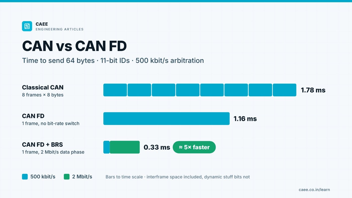
Send 64 bytes of data with 11-bit identifiers, with arbitration at 500 kbit/s:
| Method | Bits on the bus | Time |
|---|---|---|
| Classical CAN, 8 frames × 8 bytes | 8 × 111 = 888 bits at 500 kbit/s | ≈ 1.78 ms |
| CAN FD, one 64-byte frame, no bit-rate switch | 579 bits at 500 kbit/s | ≈ 1.16 ms |
| CAN FD, one 64-byte frame, 2 Mbit/s data phase | 29 bits at 500 kbit/s + 550 bits at 2 Mbit/s | ≈ 0.33 ms |
With a 2 Mbit/s data phase, the 64 bytes arrive about five times sooner than with classical CAN. Even without a bit-rate switch, CAN FD is about 1.5 times faster because it pays the frame overhead once instead of eight times: 512 of the 579 bits (88 %) carry data, against 64 of 111 bits (58 %) in a classical frame.
How the bits add up (the 3-bit interframe space is included; dynamic stuff bits are not, because they depend on the data):
- Classical frame: SOF 1, ID 11, RTR 1, IDE 1, r0 1, DLC 4, data 64, CRC 15, CRC delimiter 1, ACK 2, EOF 7, interframe space 3 = 111 bits.
- CAN FD frame at the arbitration rate: SOF 1, ID 11, RRS 1, IDE 1, FDF 1, res 1, BRS 1, ACK 2, EOF 7, interframe space 3 = 29 bits.
- CAN FD frame at the data rate: ESI 1, DLC 4, data 512, stuff count 4, fixed stuff bits 7, CRC 21, CRC delimiter 1 = 550 bits.
Hardware you need
- A CAN FD controller on every node, such as the FDCAN peripheral on STM32G4.
- CAN FD transceivers. A transceiver designed for classical CAN may not meet the timing needed at 2 Mbit/s and above. The Microchip MCP2562FD, for example, is specified for CAN FD up to 8 Mbit/s.
- A clean topology. In the data phase only one node transmits, so the bit no longer has to cover a round trip over the whole bus. What limits the data rate instead is signal quality: ringing from long stubs and asymmetry in the transceivers. Keep stubs short and terminate both ends of the bus with 120 Ω.
- Transmitter delay compensation (TDC). At high data rates the delay through your own transceiver becomes a large part of a bit. CiA 601-3 recommends enabling TDC for data rates above 1 Mbit/s, with a data-phase prescaler of 1 or 2.
Mixing classical and CAN FD nodes
A CAN FD controller sends and receives classical frames too, so you can move a network to CAN FD step by step. The catch: a classical-only CAN controller cannot decode the faster, longer part of a CAN FD frame. It sees errors and sends an error frame, which destroys the CAN FD frame. In practice, every node on the bus must be CAN FD-capable (or specifically designed to tolerate CAN FD frames) before any node sends them.
Which one should you use?
- Classical CAN suits low-rate control and status signals that fit in 8 bytes, existing networks and ECUs, and microcontrollers that only have bxCAN.
- CAN FD suits messages with more data (sensor data, calibration data), faster ECU software updates over CAN, and messages that must carry security data. AUTOSAR Secure Onboard Communication (SecOC), for example, adds a freshness value and a message authentication code to each protected message — hard to fit into 8 bytes.
- CAN XL, also defined in ISO 11898-1:2024, goes further with data fields of up to 2048 bytes. It is newer; CAN FD is today's usual step up from classical CAN.
CAN FD on STM32G4 with the HAL
An 80 MHz FDCAN clock with a prescaler of 1 in both phases follows the CiA recommendations:
/* 80 MHz FDCAN clock, prescaler 1 in both phases (tq = 12.5 ns) */
hfdcan1.Init.FrameFormat = FDCAN_FRAME_FD_BRS;
hfdcan1.Init.NominalPrescaler = 1;
hfdcan1.Init.NominalTimeSeg1 = 127;     /* 1 + 127 + 32 = 160 tq = 500 kbit/s, sample point 80 % */
hfdcan1.Init.NominalTimeSeg2 = 32;
hfdcan1.Init.NominalSyncJumpWidth = 32;
hfdcan1.Init.DataPrescaler = 1;
hfdcan1.Init.DataTimeSeg1 = 29;         /* 1 + 29 + 10 = 40 tq = 2 Mbit/s, sample point 75 % */
hfdcan1.Init.DataTimeSeg2 = 10;
hfdcan1.Init.DataSyncJumpWidth = 10;
/* ... remaining fields, then HAL_FDCAN_Init(&hfdcan1) ... */

/* after HAL_FDCAN_Init(), before HAL_FDCAN_Start(): TDC offset = data sample point in clock periods */
HAL_FDCAN_ConfigTxDelayCompensation(&hfdcan1, 30, 0);   /* (1 + 29) x 1 */
HAL_FDCAN_EnableTxDelayCompensation(&hfdcan1);
The right data-phase sample point depends on your transceivers and topology (CiA 601-3 explains how to calculate it); 75 % is only a starting point. Setting the TDC offset to the data-phase sample point is also what the Linux kernel's CAN driver does.
Sending a 64-byte frame with bit-rate switching:
FDCAN_TxHeaderTypeDef tx = {0};
uint8_t payload[64] = {0};

tx.Identifier = 0x123;
tx.IdType = FDCAN_STANDARD_ID;
tx.TxFrameType = FDCAN_DATA_FRAME;
tx.DataLength = FDCAN_DLC_BYTES_64;
tx.ErrorStateIndicator = FDCAN_ESI_ACTIVE;
tx.BitRateSwitch = FDCAN_BRS_ON;
tx.FDFormat = FDCAN_FD_CAN;
tx.TxEventFifoControl = FDCAN_NO_TX_EVENTS;
tx.MessageMarker = 0;

if (HAL_FDCAN_AddMessageToTxFifoQ(&hfdcan1, &tx, payload) != HAL_OK)
{
  /* Tx FIFO full: try again later */
}
For the nominal bit-timing calculation step by step, see CAN bit timing on STM32G4 at 500 kbit/s.
Sources
- ISO 11898-1:2024 Road vehicles — Controller area network (CAN) — Part 1: Data link layer and physical coding sublayer
- ISO 11898-1:2015 (the edition that added CAN FD; now withdrawn)
- Robert Bosch GmbH, CAN with Flexible Data-Rate Specification, Version 1.0, 2012
- CAN in Automation, CiA 601 series: CAN FD guidelines and recommendations
- H. Zeltwanger, Recommendation for the CAN FD bit-timing, CAN Newsletter, March 2018
- STMicroelectronics, AN5348 Introduction to FDCAN peripherals for STM32 MCUs
- STMicroelectronics, STM32CubeG4 HAL driver, stm32g4xx_hal_fdcan.c
- Linux kernel, drivers/net/can/dev/calc_bittiming.c (can_calc_tdco)
- Microchip, MCP2562FD high-speed CAN FD transceiver
- AUTOSAR, Specification of Secure Onboard Communication (SecOC)
All articles · CAN / CAN-FD Internship · FOC Motor Control Internship · Free workshops